
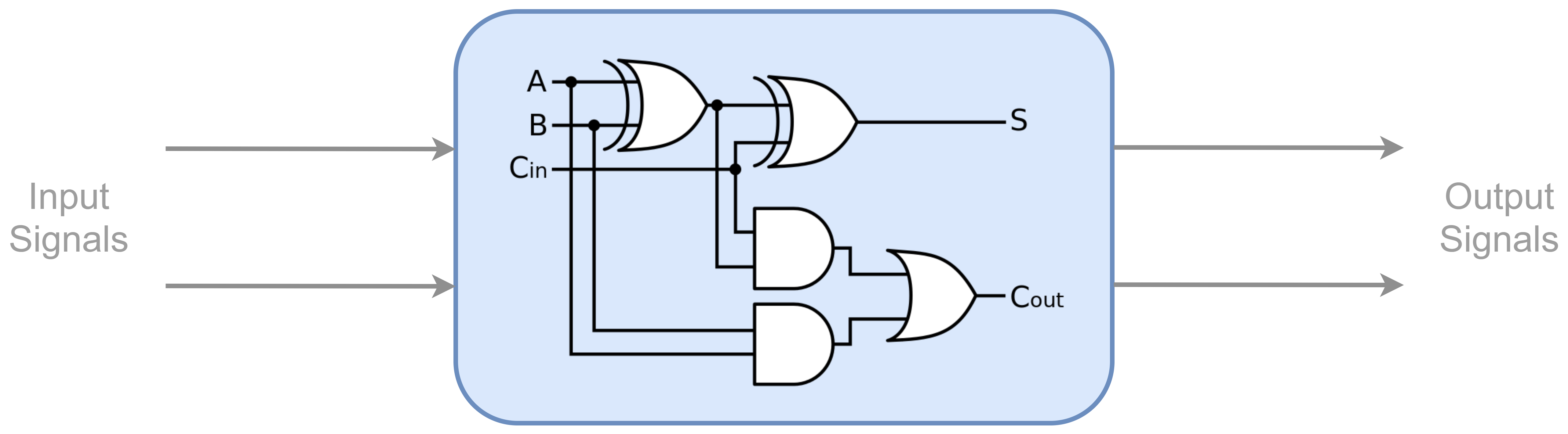
If entities are the black box representation of a system, the architecture is the white box representation. It contains all of the logic, registers, and wires that determine the function of the digital system. The diagram below represents the function of the architecture. In the previous lesson, the entity represented a blank box with input and outputs, where nothing of the internal system was known. Conversely, the architecture represents the contents of the box and knows nothing of the external conditions, other than what is fed to it by the entity.
The architecture is made up two parts: the declaration and the body. The declaration contains the initializations of all objects including constants, signals, types, etc. The body represents the actual logic and hardware that is to be implemented in the FPGA. In general, an architecture is defined as such:
architecture arch_name of entity_name is
-- Declarations
begin
-- Body
end architecture arch_name;
Every architecture must have a name, denoted as arch_name, and an associated entity, denoted as entity_name. The architecture will have access to all of the ports defined for the specified entity. Below is an example of a very basic entity and architecture pair, where the entity is being reused from Lesson 1.
entity LedController is
port (
Button1 : in std_logic;
Switch1 : in std_logic;
Led1 : out std_logic
);
end LedController;
architecture LedControllerArch of LedController is
constant Enable : std_logic := 1; -- Controls if system is enabled
begin
-- Update Led1 if the system is enabled
Led1 <= (Button1 xor Switch1) and Enable;
end architecture arch_name;
In the Declaration portion of the architecture, we have defined a constant called “Enable”. Constants will be discussed in more detail in future lessons; however, the value of constants do not change when the code is synthesized into the FPGA. In this part of the code, we are simply stating WHAT Enable is, and do not actually take any action with it.
In the Body portion of the architecture, we use several objects to perform some logic and an assignment. Some of the objects including Led1, Button1, and Switch1 have been defined as ports in the LedController entity. The Enable object was defined in the Declaration portion of this architecture. All objects that we use in the Body part must be defined in either the associated entity or the architecture’s declaration section. In this part of the code, the VALUE of each object is utilized and manipulated. Whereas, in the Body potion, a value may be assigned to an object, but is not used.
The entity and architecture together make up the basic structure of a VHDL component. If we want the code to actually compile, all we need to add is the basic IEEE library to the top of the code. This allows us to use the std_logic type.
library ieee;
use ieee.std_logic_1164.all;
Now that we have the concept of entities and architectures down, we can delve into the details. In the next lesson, we will discuss VHDL Data Types.